Next: Web Interface Up: User manual Previous: User manual Contents
HERMES is a telecommunication system which operates in the High Frequency (HF) band. HERMES allows digital multimedia exchange between users and stations, including exchange of text, image, audio or any other file type. The system interface to the users is a web interface available to users within WiFi connectivity distance to a HERMES transceiver.
The system relies heavily on the e-mail protocol, which can be managed and accessed thought the system's web interface or through specialized apps, like DeltaChat1.1. HERMES also supports peer-to-peer secure messages between the Host stations, which works as a bulletin board system (BBS).
The system employs a star topology network in which a Gateway station connects to all Host stations in remote locations. The Gateway station routes e-mail and other messages locally (back to Host stations over HF) or over the Internet to the wider world. The synchronization between the data to be sent or received from each remote station is asynchronous and orchestrated by the Gateway station in a round-robin fashion (one Host station after another, in order) during pre-established times.

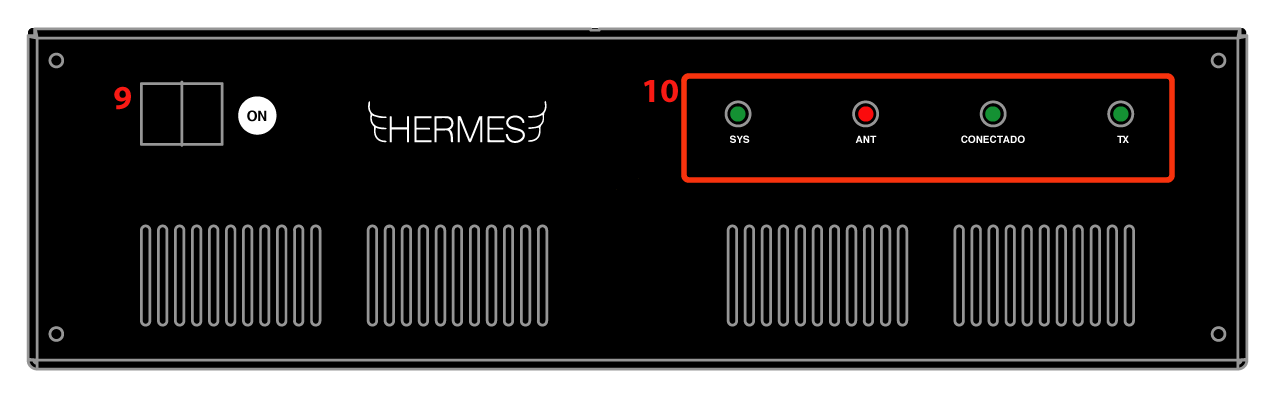
The front panel of the equipment is shown in Figure 1.2.
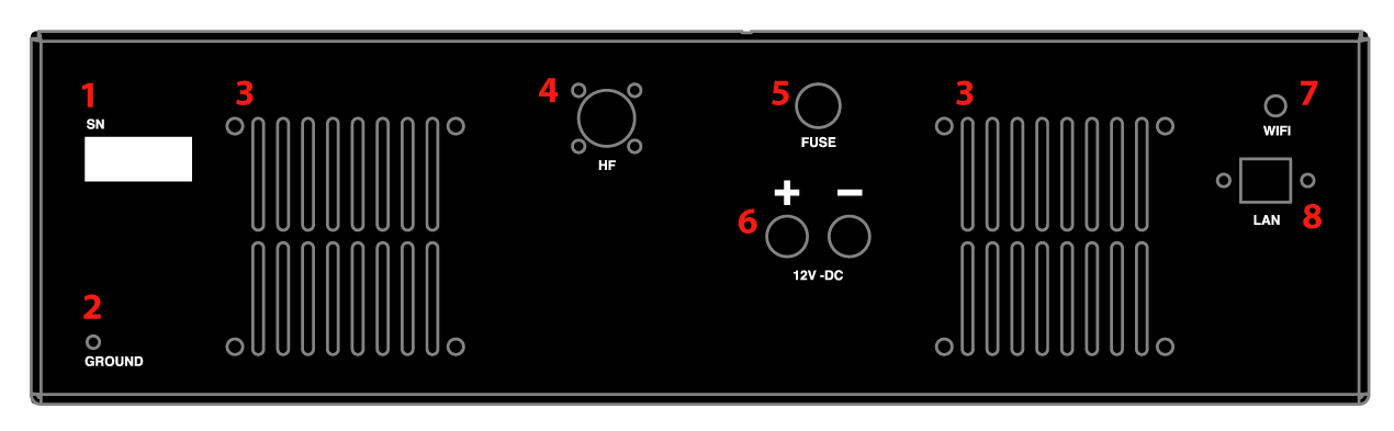
The HERMES box includes the following input / output interfaces, as shown in Figure 1.1.
The LED indicator lights are set to show the following:
An HF antenna tuned to the desired operating frequency must be connected to the equipment. Never turn on the equipment without first connecting to an appropriate antenna!
There are many HF antennas, each one fitting a different purpose. For short and medium range communications (up to about 800 km), a quarter wavelength dipole installed in inverted V configuration is a good and affordable option.
The system is designed to operate with between 12V DC to 14V DC power. A typical setup would use 12V DC from a battery connected to a solar charge controller and photo-voltaic panels. Another setup option is to use a 12V or 13.8V AC/DC power supply.
The red connector on the back of the transceiver should be connected to the positive (+) polarity of the battery or power supply unit, while the black connector to the negative (-) polarity. The system has polarity inversion protection, but care should be taken to proper power installation of power connections. The transceiver consumes approximately 2A in receive mode, and 6A in transmit mode.