Next: RF test Up: sBitx installation guide Previous: WiFi Setup Contents
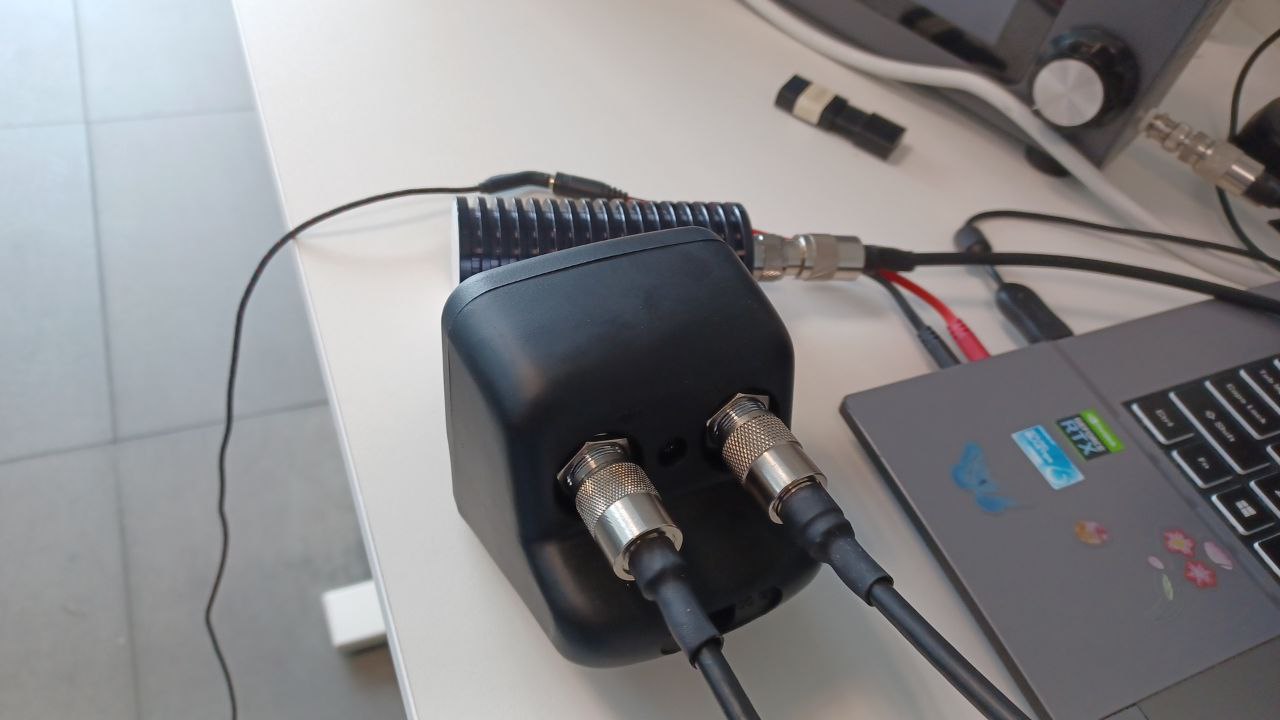
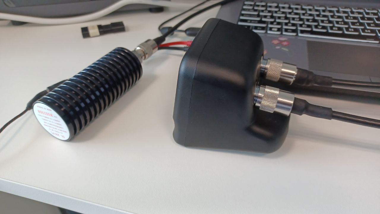
For proper testing, the radio needs to be connected, ideally, to a power meter (also called wattmeter), which should be connected to a dummy load, as shown in Figures 2.26 and 2.27.
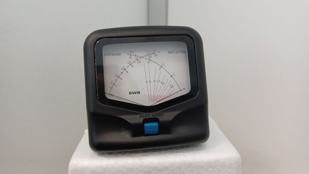
The radio (sBitx) has a BNC female connector, and needs the appropriate cables and adapters to be connected to the Wattmeter and dummy load (eg. by using BNC Male to UHF/SO239 Female). The wattmeter measures the forward and reflected power of the radio, and the dummy load simulates an antenna without radiating the signal.
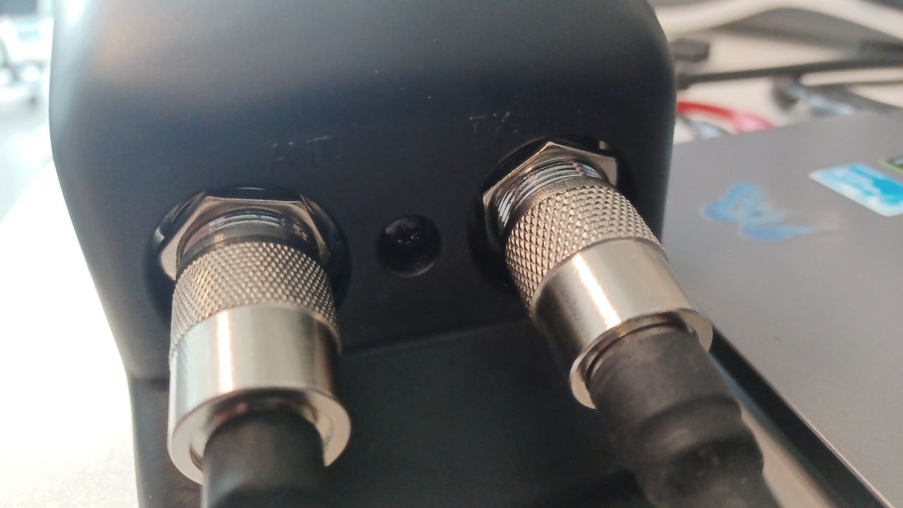
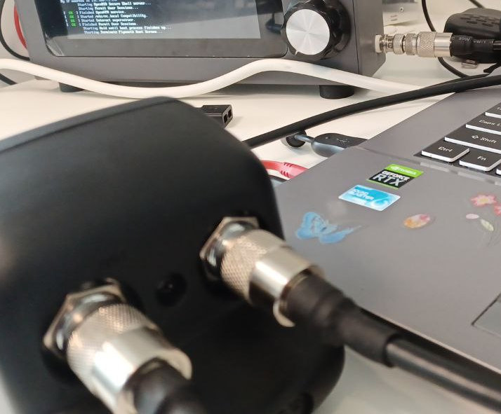
The radio needs to be connected (see Figure 2.29) to the “TX” or “Transmitter” (see Figure 2.28) port of the power meter, while the dummy load should be connected to the “ANT” or “Antenna” port.
Make sure the cables are properly connected and the front of the power meter (Figure 2.30) is in a visible position.